01 / Engineering case study
Automated Antenna Radiation Pattern Measurement System
Automated angular scanning and RF data acquisition for antenna pattern analysis.
- Engineering domain
- RF instrumentation & automation
- Project status
- Completed
Developed by Mohammed Vashir - Difficulty
- Research Level
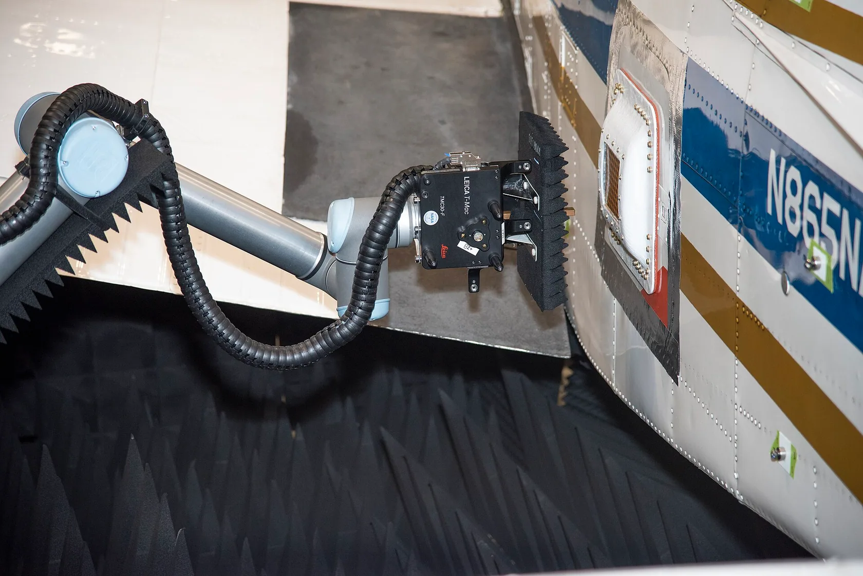 Representative imagery — not this 4TECH build.
The problem.
Comparing antennas requires measurements that relate received signal level to orientation. Manual rotation and separate readings make it difficult to maintain a consistent sequence and reconstruct the resulting pattern.
The engineering approach.
The system brings motorized positioning, an RF detector and microcontroller acquisition into one workflow. ESP32 firmware coordinates angular steps with readings from the AD8317 detector, while the measurement interface presents observations and supports data export.
Engineering work covers the motor-driver interface, sensor acquisition, scan sequencing and the transfer of readings into a structured dataset. The resulting architecture connects the mechanical angle, electronic measurement and software visualization so that a scan can be examined as a complete engineering record.
The toolkit.
- ESP32
- AD8317
- NEMA17 / A4988
- nRF24L01+
- Python
- CSV acquisition
Engineering contribution.
Provides a practical antenna-characterization workflow and a reusable platform for RF measurement experiments.
Project documentation
What the record supports.
This record draws on the owner's project description, résumé and earlier development notes. It describes the engineering scope without treating an unshared dataset as a measured result.
Motorized positioning
Reported observationThe motor setup was reported working during prototype development. No angular repeatability log is included.
RF acquisition workflow
Described workThe ESP32, AD8317 detector, NEMA17/A4988 drive and nRF24L01+ link are described alongside display, visualization and CSV-export work.
Radiation-pattern result
Not verifiedA calibrated angular dataset, reference setup and repeatability analysis have not been supplied for publication.
Technical scope & validation
Radiation patterns depend on the measurement environment, reference source and calibration procedure. No numerical gain accuracy or certified frequency coverage is specified here.
What would verify performance
- Record the angle reference, step size, RF source, detector calibration and measurement environment.
- Export raw sweep data and repeat the scan under the same conditions to establish repeatability.
- Publish the setup photograph, CSV and plotted pattern together so the result can be checked.
Have a related challenge?
Start with your goal. We will work through the possibilities.